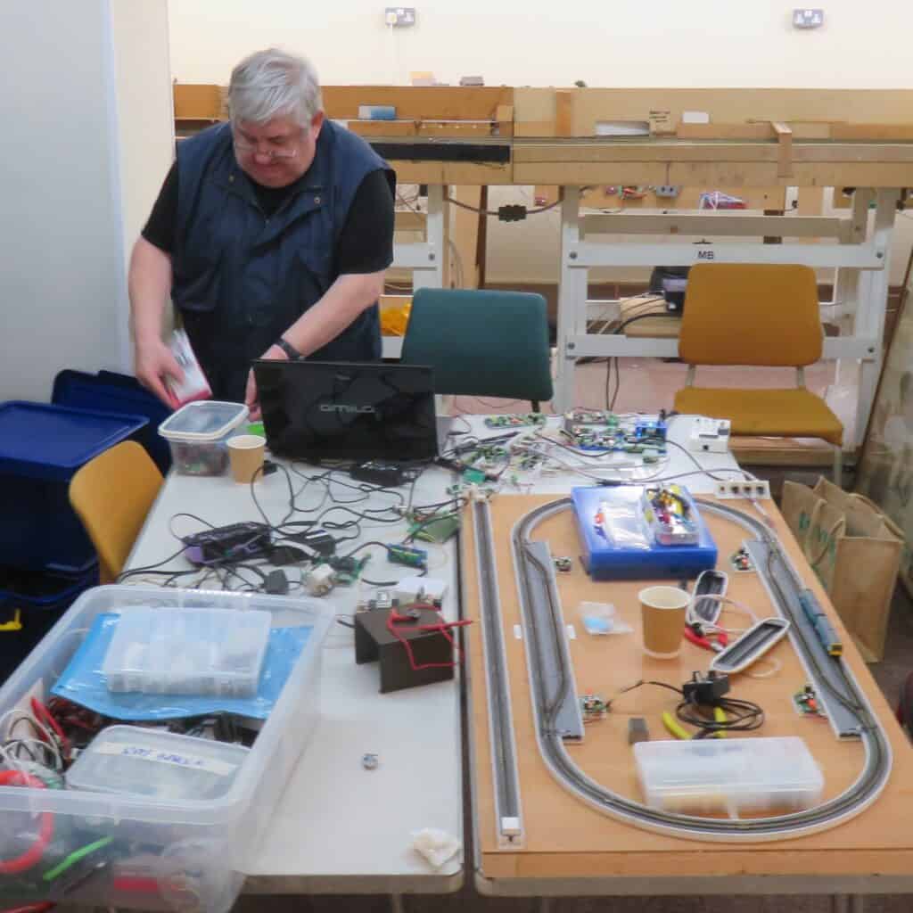
Ray took the lead on getting the latest tangle of electronic modules to work.
Previously, DCC had been trialed on the Test Board and this time the layout control bus was configured to enable the servo driven points to be changed and to route the train occupancy information.
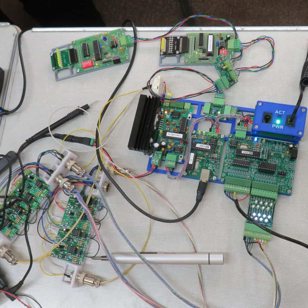
The new boards on the left are current sensors. When a loco is in one of the four sections of the oval, current is drawn and the detector boards light up. Two boards light up as the loco leaves one section and enters the next.
The boards on the top are temporary to provide switches to change the points and to provide another set of LEDs for additional train occupancy displays.
The large board provides the DCC power, the USB interface to the computer and the track occupancy inputs.
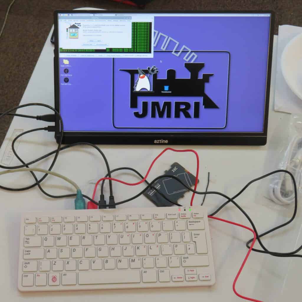
At the end of the afternoon, Allan disconnected Ray’s PC and connected in a Raspberry Pi running the automation software JMRI and was able to demonstrate control of the DCC loco from his mobile phone.
In retrospect, this was all the more imnpressive, when it was realised that no configuration had taken place. JMRI worked, out of the box, successfully recognising the MERG DCC controller and applying the correct configuration without any operator input.
Operation of the points and creation of a layout diagram does require some hands-on activity and that will be a task for later this month.