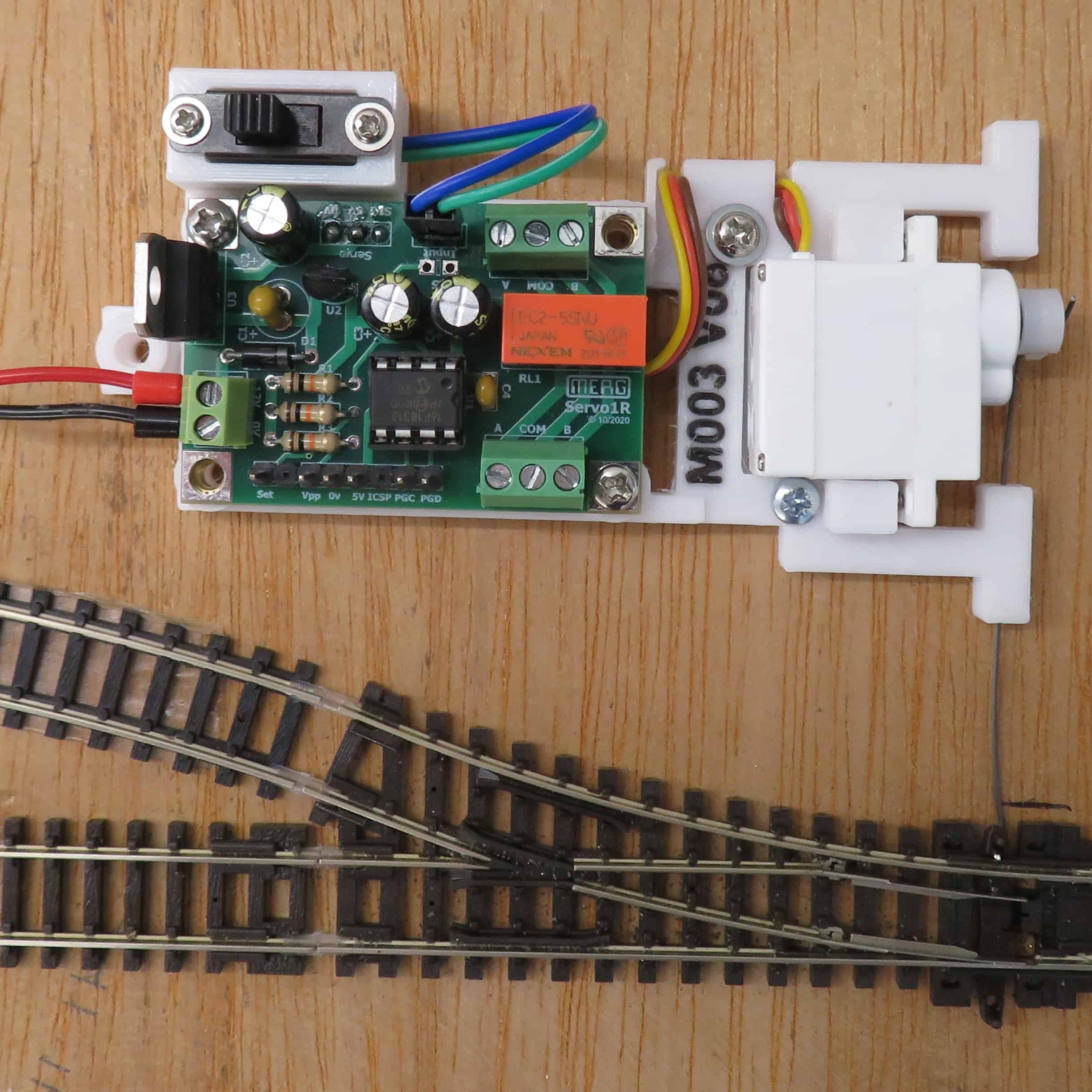
Malcolm H has been busy installing the first point on Test Track 1.
There is a control box that is connected to the control board and used to set the start point, end point and speed at which the tie bar moves.
We did have a loop in the wire, connecting the servo to the point, to absorb any excess force, but this had to be removed as it prevented the servo overcoming the spring in the point.
The slider switch can be used to change the point manually until such time as the control unit is connected which will drive the loco and the points.
All Allan has to do now is remember where he stored the other three servo controllers!

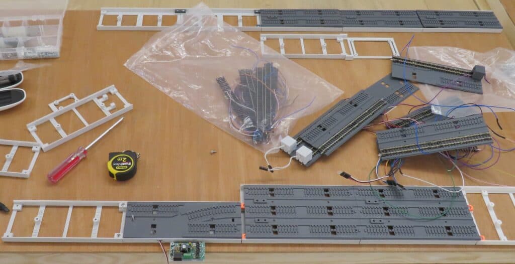
Some initial activity on Test Track 2 was evident.
Test Track 1 uses double sided sellotape to temporarily fix the track to the board. This board will use 3D printed raised ballast to secure the track and provide space under the track to run the droppers and point control wires.
The layout will be a U shape and the start of the two straight sections can be seen in the photo above.
The 3D prints for the curves have yet to be designed – watch this space.
Both these tracks will be available to members who want to experiment with electronics in safety – away from their cherished layouts!

