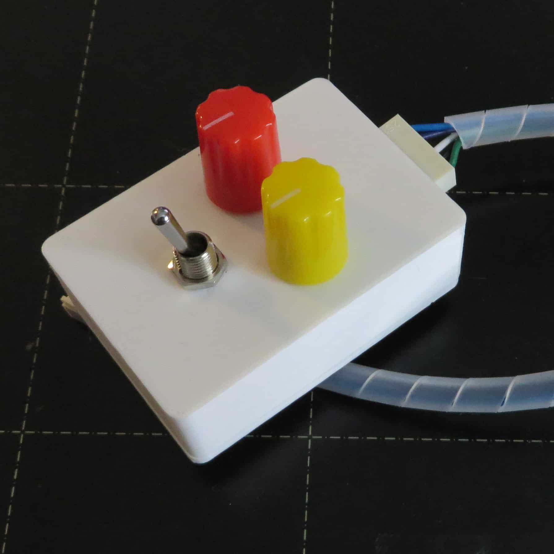
A PC and a bank of eight switches have been used to help the the start and end points for the servos on each point. The positioning of the servos is set using a single setter box – see photo which is connected to each controller board in turn and the limits of the servo movements are adjusted.
The last step is to connect the train detectors to the PC.

These are the modules that will be used to capture the signals from the DCC current detector units and encode them into CBUS messages which in turn are input to a computer through an USB interface.
The module is capable of eight inputs and has the capability of adding a daughter board to extend the number of inputs to 16. However the daughter board is plugged on top of the main board and there is not enough clearance under the board for the combined height. The solution is to connect two of these boards rather than one plus a daughter board.
When the installation and wiring of these two boards are complete, a PC will be able to change the points and detect trains on the track. That is all of the electronics required for the moments – that is until signals are installed at some point in the coming weeks.